
2023/01/25
2023/02/22 改定
2023/03/02 追加
電圧の時間変化を調べる必要が発生した。僕のオモチャ箱の中に、まだ一度も使ったことのない Arduino uno R3 が転がっていたので、それを使うってみることにした。Raspbery Pi (RasPi) は我が家では既に動いている。僕は Pi1, Pi2, Pi3 を持っている。愛用しているのは Pi2B である。Pi1 は非力で Plan9 でしか使い物にならない。Pi3 は電気を食い過ぎる。2.6A の 5V 電源が必要である。そこで 2A の 5V 電源で足りる Pi2 を使うことにして、Arduino IDE をインストールした。実を言えば、僕は IDE なるものは大嫌いなのだが、情報の多い IDE からスタートすることにしたのである。
インストールした Arduino IDE は 1.8.18 である。
次のメッセージは気にしなくてもよいらしい:
touch: cannot touch '/root/.config/mimeapps.list': No such file or directory
/usr/bin/xdg-mime: 848: /usr/bin/xdg-mime: cannot create /root/.config/mimeapps.list.new: Directory nonexistent

 done!
RasPi で Arduino IDE を使ったらハングした。(mouse がハング)
RasPi をリブートしたら Arduino IDE が動作しだした。
Arduino では、Aruduino で実行される プログラムのことを sketch と言う。
文法は C 言語風
ファイル拡張子は .ino
次の文献は基本的である。
[1] Arduino Sketches
https://docs.arduino.cc/learn/programming/sketches
[2] Language Reference
https://www.arduino.cc/reference/en/
sketch 毎にディレクトリを作成する必要がある。
sketch の例
int ledPin = 13;

void setup()
{
	pinMode(ledPin, OUTPUT);      // sets the digital pin as output
}

void loop()
{
	digitalWrite(ledPin, HIGH);
	delay(5000);
	digitalWrite(ledPin, LOW);
	delay(1000);
}
図1: sketch b0.ino
C 言語ではないので、main() 関数は要らない。sketch の説明の前にピン配置を示す1。
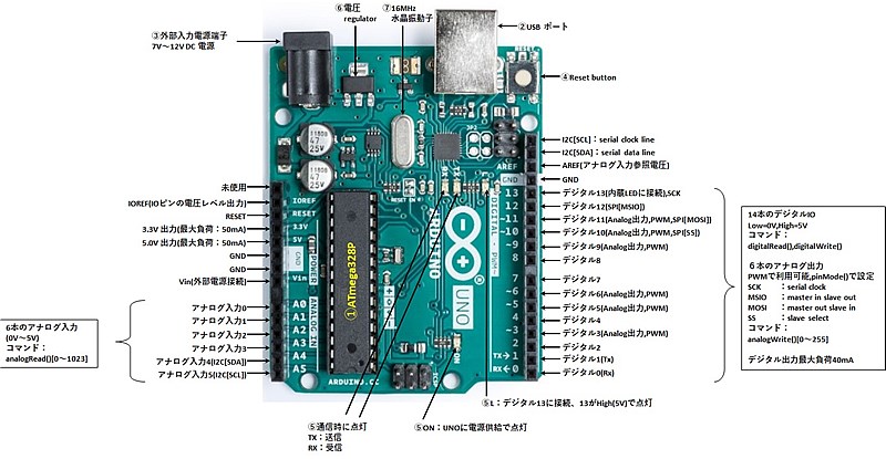
図2: ピン配置
ボード上にいくつか LED が埋め込まれていて、13番ピンで点灯/消灯を制御できる。
delay(5000)
RasPi と Arduino を USB で接続しておく必要がある。Arduino の電源は USB から採られる。
b0.ino をマウスでクリックすると IDE が立ち上がり
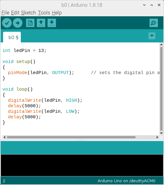
図3: Arduino IDE
が表示される。
図には File Edit Sketch Tools Help のメニューが表示されている。Sketch メニューのサブメニューの中に
Verify/Compile
Upload
...
Serial Monitor
Serial Plotter
https://omoroya.com/arduino-extra-edition-02/
僕は電圧のデシタル表示を行う測定器を3つ持っている。その結果と Arduino を比較する。Arduino のアナログピンの電圧は 0 から 1023 までの数値として得られるが、これは 0V から 5V を表している。従ってアナログピンの数値を x とすれば、電圧は
5*x/1023
測定対象として適当な電池を使った。基準電圧を出す素子を持っていないのでどれが正しいのかはっきりしないが参考にはなる。
DT830B	1.342
MS8218	1.3373
MS8268	1.332
Arduino	1.320
このうち、MS8218 は(昔買った)高価な(高性能を謳う)製品である。これを基に考えてもよいのかも知れない。
MS8218	0.03%
MS8268	0.7%
となっている。(DT830B の取扱説明書には精度に関する情報がない)
この測定はできるだけ Arduino の近くで行われた。測定対象が Arduino から離れると、電圧の測定は微妙で悩みの種である。工夫を凝らす必要がある。
Arduino は6個のアナログピンを持っている。これらのピンに同一の電圧を与えて測定しても同一の電圧を示す保証はない。分解能から 5mV の誤差が発生しているので、例えば 1.315 であったり、1.320 であったりする。1V 程度の電圧を測定している場合には、ピン毎に 1% 程度の誤差を覚悟しなくてはならない。これが許容範囲を超えているときには、諦めるか、あるいは特別の工夫が要求される。
空きピンは隣接するピンの影響を強く受ける。
アナログピン A0 から、4秒毎に電圧を読み取り、その結果を RasPi に渡す sketch の例を次に示す。
アクセスのタイミングが判るように led を点滅させている。
このプログラムは基本的である。
int ledPin = 13;
int analogPin = A0; // A0 is 0
int val = 0;
int count = 0;

void setup()
{
	pinMode(ledPin, OUTPUT);
	Serial.begin(9600);
}

void loop()
{
	count++;
	digitalWrite(ledPin, HIGH);
	Serial.print(count,DEC);
	val = analogRead(analogPin);  // read the input pin
	Serial.println(val);          // debug value
	delay(3000);
	digitalWrite(ledPin, LOW);
	delay(1000);
}
譜1: Serial 通信を行う sketch の簡単な例
ここで言う Serial とは、RasPi と Arduino を結ぶ USB コードの中を流れるシリアル通信路のことである。昔ながらの RS232C 形式のデータが、USB 形式のデータの中に埋め込まれているはずである。このデータは RasPi からは /dev/ttyACM0 を経由して Arduino IDE に渡される。このデバイスファイルはコマンド
ls -l /dev
Arduino から送られてきたデータは IDE の Tools の "Serial Monitor" を使えば見ることができる。この機能はsketch のデバッグに使える。ここに表示されるものが、ファイルに落とせるならデータロガーとして使えるのである。しかし... Arduino IDE は気が利かない。ファイルに落すメニューが無いばかりでなく、Monitor に表示されている文字データのコピーさえもできないのであめ。
何とかならないか?
次のプログラム sermon.c がこの問題を解決する。RasPi 上で
cc -o sermon sermon.c
sudo ./sermon /dev/ttyACM0
sudo ./sermon /dev/ttyACM0 | tee xxxx.xxx
/*
 * sermon ver. 1.1
 * -Kenar-
 */

#include <stdio.h>
#include <stdlib.h>
#include <sys/types.h>
#include <sys/stat.h>
#include <fcntl.h>
#include <string.h>
#include <unistd.h>
#include <time.h>
#include <ctype.h>
#define bufsiz 1024

char *arg0;

void
usage()
{
	fprintf(stderr,"usage: sermon [file]\n");
	// example: sermon /dev/ttyACM0
	exit(3);
};

void
dump(char *data, int n)
{
	int i,c;
	for(i=0;i<n;i++){
		c = data[i];
		if(iscntrl(c))
			fprintf(stderr," %02x",c);
		else
			fprintf(stderr,"%2c",c);
	}
	fprintf(stderr,"\n");
}

/*
*	readln(fd,buf,sizeof buf)
*	read fd until '\n' (including '\n')
*	data in the buf end with LF. CR codes are removed.
*/
int
readln(int fd, char *buf, int nb)
{
	int i,j,n;
	static char buf0[bufsiz];
	static int mb = 0; /* data size in buf0 */
	char *sp = buf;
	char *ep = buf+nb;
	memcpy(buf, buf0, mb);
	sp = buf + mb;

L1:;

	n = read(fd,sp, ep - sp);
	if(n < 0)
		return -1;
	if(n == 0){ /* unix read() doesn't wait incoming data */
		sleep(1);
		goto L1;
	}
	//dump(sp,n); /* NOTE1: you will find that '\r' from arduino is converted to '\n' */
	sp[n]  = 0;	// used for debugging
	//write(2,"#",1);write(2,sp,n); // debug
	//fprintf(stderr,"(%d,%d,%d,%d,%s)\n",n,sp[0],strlen(sp),ep-sp,sp); // debug
	while(n > 0){
		if(*sp == '\n'){
			sp++;
			n--;
			mb = n;
			memcpy(buf0,sp,mb);
			if(n != strlen(sp)) // debug
				fprintf(stderr,"###\n");
			return sp - buf;
		}
		sp++;
		n--;
	}
	sleep(1);
	goto L1;
}

int
writetime(int fd) /* write current time to fd */
{
	time_t t;
	int n, nt;
	char tbuf[32]; // for time()
	t = time(NULL);
	nt = snprintf(tbuf, sizeof tbuf, "%ld ", t);
	if(nt < 0){
		fprintf(stderr,"out of tbuf size\n");
		return -1;
	};
	n = write(fd,tbuf,nt);
	return n;
}

int
main(int argc,char *argv[])
{
	int fd = 0;
	ssize_t n;
	char rbuf[bufsiz]; // for readln()
	arg0 = argv[0]; // executable file name of this file
	argc--;argv++;
	if(*argv[0] == '-' ||  argc > 1)
		usage();
	if(argc){
		fd = open(argv[0],O_RDONLY);
		if(fd<0){
			fprintf(stderr,"%s not open\n",argv[0]);
			exit(3);
		}
	};
	while(1){
		n = readln(fd,rbuf,bufsiz);
		if(n < 0)
			exit(3);
		if(n == 1) /* we need this one. look NOTE1 */
			continue;
		//fprintf(stderr,"# %d\n",n); // debug
		rbuf[n] = 0;
		writetime(1);
		write(1,rbuf,n);
	};
	exit(0);
};
譜2: sermon.c (ver.1.1)
このプログラムは、1秒毎に /dev/ttyACM0 を見に行って、データが送られていれば、それを読み取り、時刻とともに表示する。できるだけ汎用性が高いように設計したつもりである。難しかったのは readln() 関数である。エラー処理はまだ十分ではないかも知れない1。
何かやっているうちに、次のメッセージに出会った:
Sketch uses 2408 bytes (7%) of program storage space. Maximum is 32256 bytes.
Global variables use 200 bytes (9%) of dynamic memory, leaving 1848 bytes for local variables. Maximum is 2048 bytes.
avrdude: stk500_getsync() attempt 1 of 10: not in sync: resp=0x00
avrdude: stk500_getsync() attempt 2 of 10: not in sync: resp=0x00
...
avrdude: stk500_getsync() attempt 10 of 10: not in sync: resp=0x00
An error occurred while uploading the sketch

This report would have more information with
"Show verbose output during compilation"
option enabled in File -> Preferences.
これについてネット上でも次のように議論されているが結論には至っていない:
avrdude: stk500_getsync() attempt 10 of 10: not in sync: resp=0x00
https://forum.arduino.cc/t/avrdude-stk500_getsync-attempt-10-of-10-not-in-sync-resp-0x00/509854
今回の場合には /dev/ttyACM0 を sermon で使用したまま sketch を upload したために stk500_getsync のトラブルが発生したらしい。
sermon を終了してから再度 upload したら問題が解決した2。
次の sketch は 1分毎に Arduino のアナログピン A1 の電圧を調べ、その結果を RasPi に送る。(単位は volt)
放電実験に使われた sketch であり、放電の停止条件を与えてあり、放電を停止したあとの電圧は最後のフィールドが "*" になっている。
#define ledPin 13
#define dPin 8 /* digital pin to stop discharge */
#define aPin 1 /* analog pin to watch */
#define stopVolt 0.9 /* voltage to switch off the load resistor */
#define delaytime1 30000 /* delay time for ledPin LED HIGH */
#define delaytime0 30000 /* delay time for ledPin LED LOW */
/*
 * stopVolt 0.9 for NiCd
 */


void setup()
{
    pinMode(ledPin, OUTPUT);      // sets the digital pin as output
    Serial.begin(9600);
    pinMode(dPin, OUTPUT);    // sets the digital dPin as output
    digitalWrite(dPin, HIGH);
}

void loop()
{
    int val;  // variable to store the value read
    float volt;
    static int done = 0;
    static int count = 0;
    static int sodone = 0;

    if(1 && !sodone){
        digitalWrite(ledPin, HIGH);
        Serial.println("=="); // sweep out garbage date in /dev/ttyACM0
        sodone = 1;
        delay(1000);
        digitalWrite(ledPin, LOW);
        delay(1000);
        return;
    }
    digitalWrite(ledPin, HIGH);
    count++;
    Serial.print(count,DEC);
    Serial.print(" ");
    val = analogRead(aPin);  // read the input pin. the val is from 0 to 1023
    volt = 5.0*val/1023;   // convert to volt. 1.588 for val=325
    Serial.print(volt, 3);
    if(done)
        Serial.print(" *");
    Serial.println("");
    if(volt < stopVolt){
        digitalWrite(dPin, LOW);
        done = 1;
    }
    delay(delaytime1);
    digitalWrite(ledPin, LOW);
    delay(delaytime0);
}
譜3: A1(analog pin 1) を監視する sketch
これを RasPi の sermon で見ると、例えば次のようになる。
pi$ sudo ./sermon /dev/ttyACM0
1676789272 ===
1676789274 1 1.271
1676789334 2 1.266
1676789394 3 1.261
...
1676843501 904 0.904
1676843561 905 0.899
1676843621 906 0.973 *
1676843681 907 0.992 *
...
最初の行はゴミを含む。従って実験を開始した時刻欄しか載せていない。